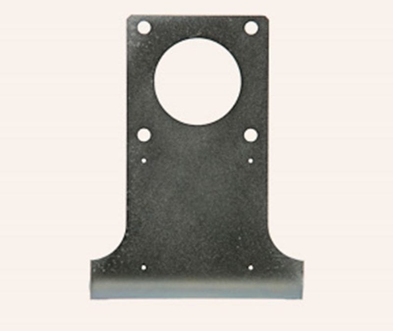
Did you know that manufacturers spend about 40% of their time fixing errors? A good portion of those errors result from design flaws. That means there is a great deal of wasted time and money when it comes to proper sheet metal design!
CAD 3d models do not always translate into excellent real-world fabrication, even if it is a relatively simple design. Even the best design engineers can run into trouble when not factoring in real-world issues. There are, however, a few major things that metal fabricators need to consider when completing sheet metal design.
The following outlines the basics of sheet metal part designs. Understanding these basics can save you wasted time and material costs between 3D CAD models or assembly drawings and actual manufacturing practices!
Common Problems of Sheet Metal Designs
Several real-world factors can affect how a project turns out during metal sheeting fabrication. In general, those are temperature, bending, and the fabrication tools being used.
A design can be spot-on on paper, but the designer must understand that real-world factors can offset tool alignments, throwing off critical dimensions and affecting the final shape. By being aware of the following real-world factors, the sheet metal designer can improve lead times, simply complicated metal designs, and reduce scrap from project errors.
The following common issues and ways to combat them can help with your next project.
- Hole Sizes
Punching holes can lead to the distortion or breakage of the metal during manufacturing.
In this case, one of the best sheet metal design tips is to punch holes whose diameter is the same or greater than the thickness of the sheet metal.
- Bend Relief
Adding a bend line to sheet metal design is a simple way to ensure the implementation of a design during a sheet metal project. A bend relief is an indentation in a straight line that makes the bending process easier and more exact.
Doing this can help prevent distortion or tearing in the final product.
To produce a minimum bend radius, the depth of the bend relief should be at least equal to or greater than the interior radius of the bend. However, the width of the bend should not be equal to or greater than the sheet thickness being used.
- Distance Between a Bend and a Hole
Another one of the best design strategies is to leave a good amount of clearance between a hole and bend. That way, you can prevent the hole from deforming when the sheet metal is bent during production.
Aim for a distance between the bend line and edge hole of at least two times the sheet metal thickness.
- Minimum Flange Widths
Ensure that your product design includes a flange width four times the thickness of your sheet metal sheets.
If you do not practice this during your manufacturing process, the finished product will have marks on its surface.
- Bending Radius
There is no singular bend radius. It will depend on the manufacturing process and the tool being used. More flexible metal (thin sheets) will yield a smaller bend radius.
A best practice when it comes to bend radius is to set it equal to its sheet thickness.
How to Fabricate Your Sheet Metal Designs
Fox Valley Stamping specializes in short run stampings, CNC laser cutting, and metal fabrication. We take your sheet metal designs and turn them into real parts and products. Learn more about our capabilities or Contact Us today.
Read Next: How to Create a Prototype for Metal Stamping


 847.741.2277
